Siemens S7 PLC
The foglamp-south-s7 plugin is a south plugin that reads data from a Siemens S7 PLC using the S7 communication protocol. Data can be read from a number of sources within the PLC
Data blocks - The data blocks store the state of the PLC
Inputs - Read the state of the inputs to the PLC
Outputs - Read the state of the outputs from the PLC
Merkers - Read from the single bit flag store
Counters - Read a counter
Timers - Read a timer
Note
If using an S7-1200 or S7-1500 PLC and the Optimized block access option for a data block is checked, the plugin is unable to read items within that block as they are no longer at fixed offsets within the block. If this option is checked we recommend using OPC UA to access the items within this block. If this is not an option then you must turn off the Optimized block access and rebuild your PLC code.
Configuring the PLC
There are a number of configuration steps that must be taken on the PLC itself to support the use of the S7 protocol.
Assigning an IP Address
Using the Siemens TIA console assign an IP address to your PLC. Connect to your PLC and locate the display of the PLC device. Double click on the network connector to bring up the properties for the network interface.
|
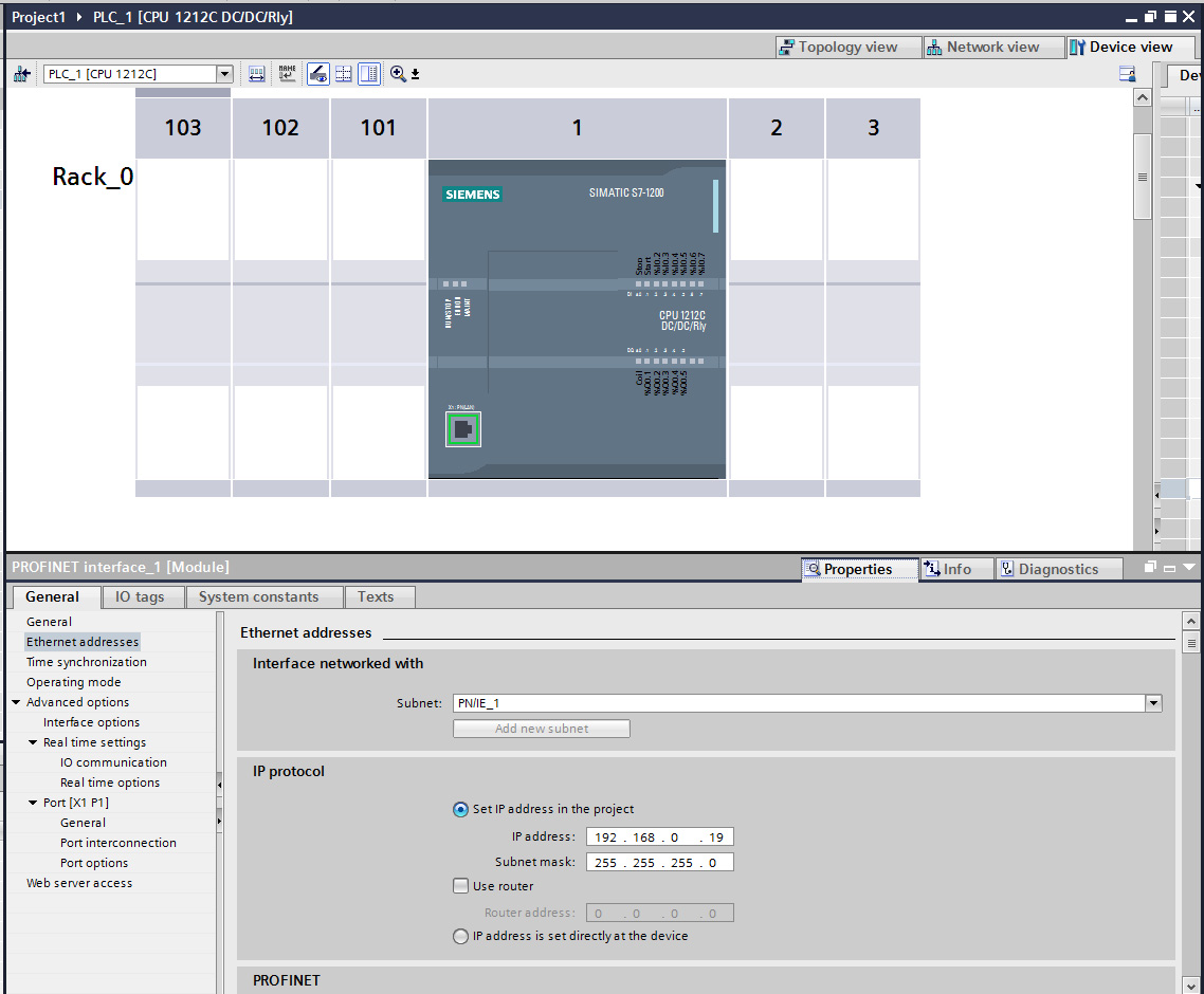
Assign an IP address to your interface and if you require it you may also assign a router to use.
Enable PUT/GET operations
The S7 1200 and 1500 series PLC’s require the PUT/GET communication from partners to be enabled in order to retrieve data using the S7 protocol. To permit the PUT/GET network operations on your PLC use the Siemens VIA tool. Note you must be sure that you are offline when you do this. Locate you PLC in the tool and right click on the device select properties and the following dialog will be displayed.
The older S7-300 and S7-400 series do not require this to be done.
|
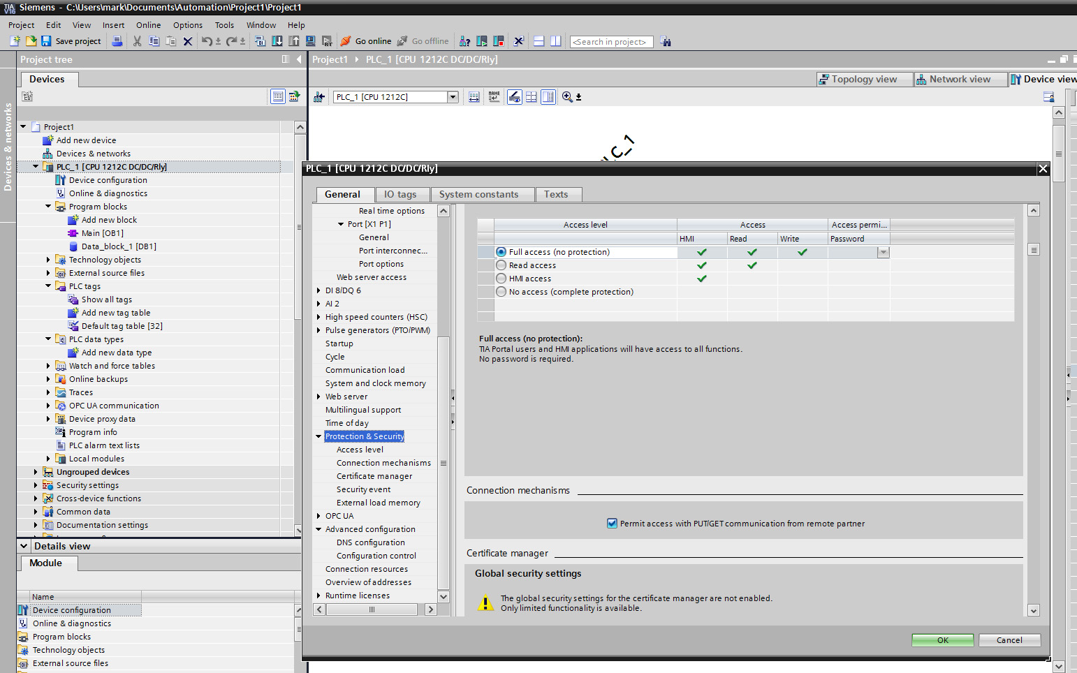
Select the protection tab and scroll down to find the checkbox that enables the use of GET/PUT operations. Make sure it is selected for your PLC.
Using the Plugin
To create a south service with the Siemens S7 plugin
Click on South in the left hand menu bar
Select S7 from the plugin list
Name your service and click Next
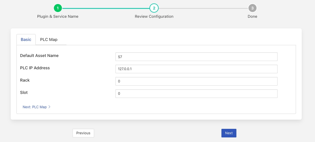
Configure the plugin
Default Asset Name: The name of the asset to use if none is given in each of the data mapping items.
PLC IP Address: The IP address assigned to your PLC.
Rack: The rack number to address, usually this is 0 for a standalone PLC.
Slot: The slot within the rack, most CPU’s are in slot 1 of the rack.
Map: The data mapping for the plugin. This tells the plugin what data to fetch from the PLC.
PLC Map
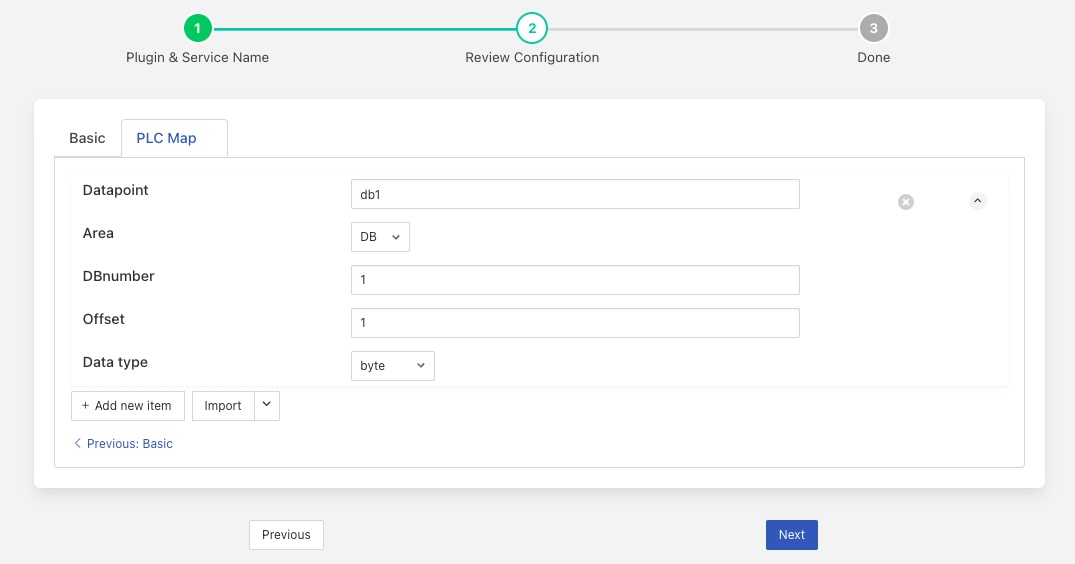
The PLC Map consists of a list of items, each of which defines how to read a tag from the PLC and what datapoint within the reading will be used to store that tag.
Each tag in the list consists of 5 items
Name |
Description |
|---|---|
Datapoint |
The name of the data point that the data will be placed in. All items must have a datapoint defined. |
Area |
The area in the PLC that data will be read from. There are a number of areas available
|
DBnumber |
The data block number, this is only required for data blocks and is used to define the block to read. |
Offset |
The offset of the start of the item within the data block. |
Data type |
The type of the data item to read. A number of different types are supported
|
A simple data mapping that wanted to read the state of two digital inputs to the PLC, say DI0 and DI2, and wanted to label these as datapoints “Stop” and “Start” within the default asset would consist of two items as follows
Item
Value
Datapoint
Stop
Area
PE
DBnumber
Offset
0
Data type
bit
And
Item
Value
Datapoint
Start
Area
PE
DBnumber
Offset
2
Data type
bit
Note
Since DBnumber is only required if the Area is set to DB we have left it blank.
In this case we set start to 0 for DI0, as it is the first digital input in the set. DI2 has a start of 2, as it is the second input. We use the type bit to return a simple 0 or 1 to indicate the state of the input. We could use byte instead, this would return the 8 inputs states encoded as a binary number.
Item
Value
Datapoint
Inputs
Area
PE
DBnumber
Offset
0
Data type
byte
Since start is set to 0 and type is byte, then we return the state of the 8 inputs.
To add in a digital output, say DO4 and label that running, we would add another item to the map
Item
Value
Datapoint
Running
Area
PA
DBnumber
Offset
4
Data type
bit
If we assume we have a data block that we wish to read data from that appears as follows
|
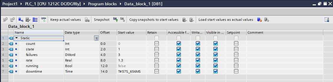
Then we can setup a number of items in the map to retrieve these values and place them in data points. The items that would read this data block would be
Item |
Value |
|---|---|
Datapoint |
count |
Area |
DB |
DBnumber |
1 |
Offset |
0 |
Data type |
int |
Item |
Value |
|---|---|
Datapoint |
state |
Area |
DB |
DBnumber |
1 |
Offset |
2 |
Data type |
int |
Item |
Value |
|---|---|
Datapoint |
failures |
Area |
DB |
DBnumber |
1 |
Offset |
4 |
Data type |
dword |
Item |
Value |
|---|---|
Datapoint |
rate |
Area |
DB |
DBnumber |
1 |
Offset |
8 |
Data type |
real |
Item |
Value |
|---|---|
Datapoint |
running |
Area |
DB |
DBnumber |
1 |
Offset |
96 Note This becomes a bit offset rather than a byte offset. |
Data type |
bool |
Item |
Value |
|---|---|
Datapoint |
downtime |
Area |
DB |
DBnumber |
1 |
Offset |
14 |
Data type |
time |
For clarity we have used the name in the data block as the datapoint name, but these need not be the same.
Interacting With The List
Each item in the list has two controls to the right-hand side of the item
|

The control on the left allows you to delete this list item. The control on the right allows the list item to be collapsed to a smaller form. When collapsed the display changes to that shown below.
|

When collapse a new icon appears, 3 dots. As shown above, hovering over this will cause a summary o the list item to be shown, clicking on it will open up the list item.
There are a number of control at the bottom of the list that can be used to interact with the list as a whole.
Add new item - clicking on this will create a new empty list item to allow another tag to be added to the list.
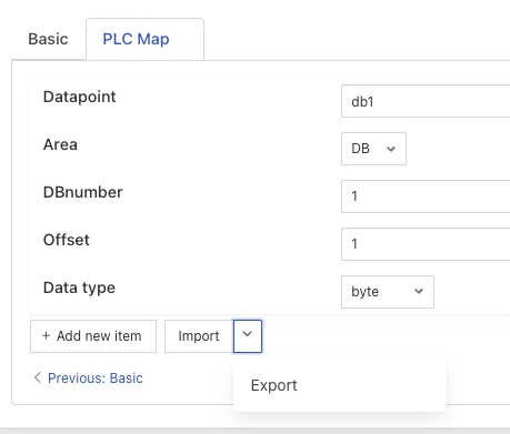
Import - clicking on this will enable a list to be imported from an external file, more detail is shown below. Clicking on the arrow next to the Import will bring up an Export option which will export the current list to a file.
Two file formats are supported for import and export, a comma separated variable (CSV) format and a JSON format.
The CSV file should contain a header row with the names of the list items and one or more rows of data
datapoint,area,DBnumber,start,type
temperature,DB,1,1,word
humidity,DB,1,8,word
The required header columns are;
Name |
Description |
|---|---|
datapoint |
The name of the datapoint in which the PLC tag will be stored |
area |
The Area in the PLC in which the tag is stored. This should be one of the areas shown in the table above. |
DBnumber |
The database block number. |
start |
The byte offset of the tag, or if the tag is a bit or bool type this is the bit offset as described above. |
type |
The type of the PLC tag. This should be one of the supported types from the table above. |
The JSON format is an array of JSON objects, each object has a property for each of the list items. The property names match the CSV header strings defined in the able above.
[
  {
    "datapoint": "temperature",
    "area": "DB",
    "DBnumber": 1,
    "start": 1,
    "type": "word"
  },
  {
    "datapoint": "humidity",
    "area": "DB",
    "DBnumber": 1,
    "start": 8,
    "type": "word"
  }
]
Clicking on the Import option will bring up a popup that allows you to select a file from your local machine or drag and drop a file onto the dialog.
|
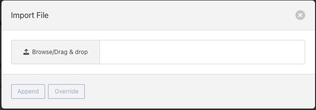
You are also presented with the option to Append the file contents to the current list of tags or Override the current list with the contents of the file.
Clicking on Export will present a dialog that request the format to export the data in.
|
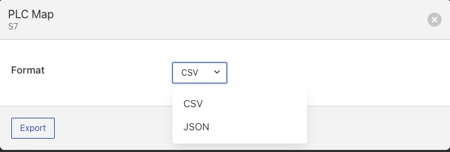
Once the format is chosen the data will be written to a file called <service name>-map with an extension of csv or json depending on the format chosen. Where <service name> is the name of the service.
PLC Map Errors
If there is an error in the map definition for a given item then that item is ignored and a message is written to the error log. For example if a bad area name is given
Jun 25 08:53:04 foglamp-18 FogLAMP S7[6121]: ERROR: Invalid area Data specified in device mapping for S7 db1-bad
Jun 25 08:53:04 foglamp-18 FogLAMP S7[6121]: ERROR: Discarded invalid item in map for datapoint db1-bad
If a Data Block is missing it’s DBnumber property then the following style of error will be produced.
Jun 25 08:39:07 foglamp-18 FogLAMP S7[6121]: ERROR: Missing data block number in map for S7, db1-bad. A data block number must be specified for a data block area read.
Jun 25 08:39:07 foglamp-18 FogLAMP S7[6121]: ERROR: Discarded invalid item in map for datapoint db1-bad
Other errors that can occur include
Jun 25 08:57:28 foglamp-18 FogLAMP S7[6121]: ERROR: Missing start in map for datapoint db1-bad
Jun 25 08:57:46 foglamp-18 FogLAMP S7[6121]: ERROR: Missing type in map for datapoint db1-bad
See Also
foglamp-south-ABB - A south plugin to pull data from the ABB cloud
foglamp-south-Beckhoff - A Beckhoff ADS data ingress plugin for FogLAMP, this monitors Beckhoff PLCs and returns the state of internal variables within the PLC
foglamp-south-ModbusC - A FogLAMP south plugin that implements modbus-tcp and modbus-rtu
foglamp-south-dnp3 - A south plugin for FogLAMP that implements the DNP3 protocol
foglamp-south-etherip - A south plugin to read tags data from a number of different Allen-Bradley and Rockwell PLCs.
foglamp-south-opcua - A FogLAMP south service that pulls data from an OPC-UA server
foglamp-south-s2opcua - An OPC UA south plugin based on the Systerel S2OPC OPC UA Toolkit. This plugin offers similar functionality to the foglamp-south-opcua plugin but also offers data encryption and authentication.