Armfield South Plugin
The foglamp-south-armfield plugin is a south plugin that connects to an Armfield device and ingest data into a FogLAMP instance, it also allows a number of control options for the Armfield device.
Configuration
The Armfield device connections to the Linux machine via a USB connection that appears as a serial port within Linux.
As with any south connection to FogLAMP the user should create a new south service for handling the connection to the Armfield device. As part of the creation of the south service select the Armfield plugin from the list. After setting the name of the south service and clicking on next a screen will appear for entering the configuration. This is divided into a number of tabs.
Connection
The Connection tab provides the configuration to attach to the device
|
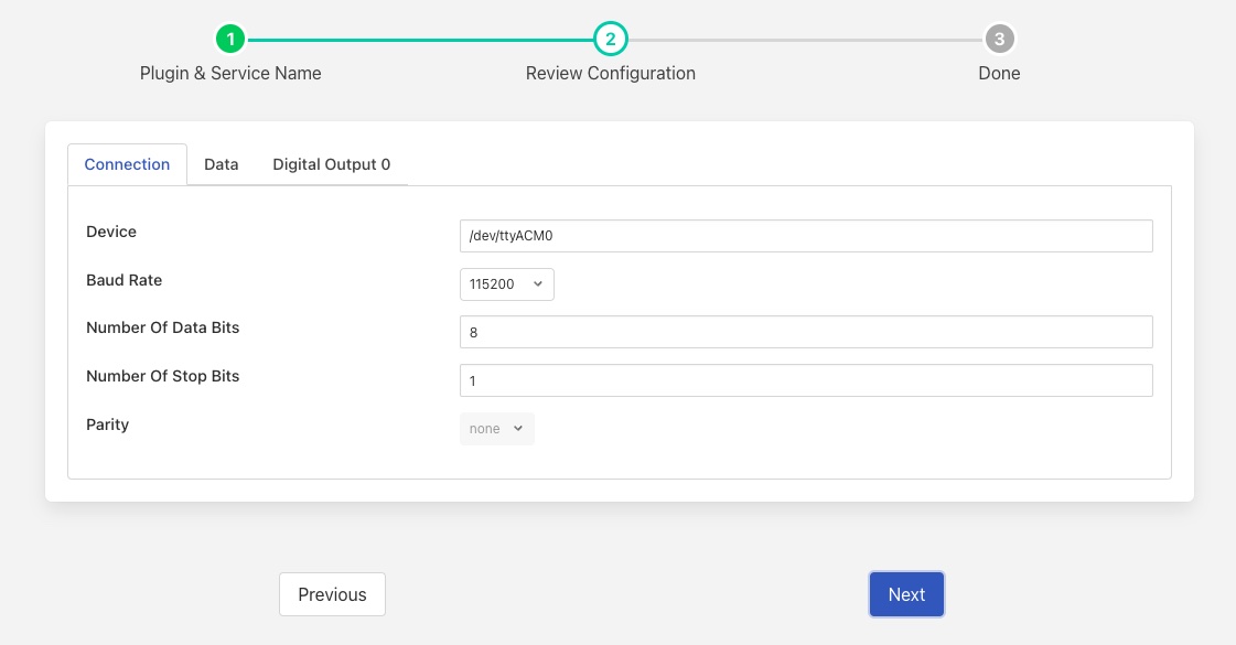
Device: - the device on the Linux machine to which the Armfield is connected.
Baud Rate: - the baud rate to use for communications.
Number of Bits: - the number of data bits to send and receive.
Number of Stops Bits: - the number of stop bits to send.
Parity: - the parity to use/accept, with 8 bit data this should be set to none.
Data
The Data tab provides configuration of the data that is returned by the plugin.
|
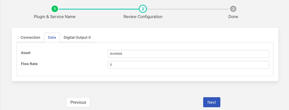
Asset: - the name of the asset that will be created in FogLAMP.
Flow Rate: - The frequency counter register that is used to read the flow rate data. It is believed that this should always be 0.
Digital Output 0
|
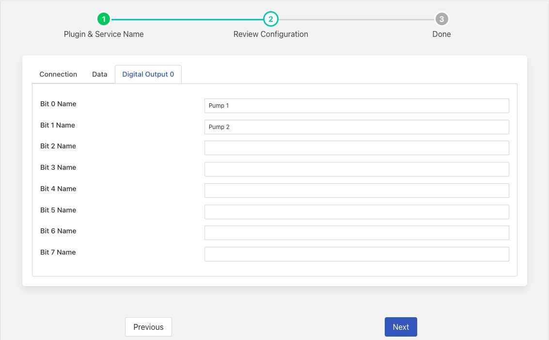
The digital outputs from FogLAMP to the Armfield device are arrange as two bit bit output channels, 0 and 1. This configuration screen allows the user to associated names with each of the output bits in channel 0. These names are then used in control write operations to control the state of the output.
Bit 0 Name: - a symbolic name for bit 0 of channel 0. This defaults to Pump 1 as this bit will turn on and off pump 1. Note a pump speed must also be set for this to take affect.
Bit 1 Name: - a symbolic name for bit 1 of channel 0. This defaults to Pump 2 as this bit turns on and off pump 2.
Bit 2 Name: - a symbolic name for bit 2 of channel 0.
Bit 3 Name: - a symbolic name for bit 3 of channel 0.
Bit 4 Name: - a symbolic name for bit 4 of channel 0.
Bit 5 Name: - a symbolic name for bit 5 of channel 0.
Bit 6 Name: - a symbolic name for bit 6 of channel 0.
Bit 7 Name: - a symbolic name for bit 7 of channel 0.
Asset Structure
When a poll request is made to the Armfield device it will read all of the analogue outputs from the Armfield, the digital output 1 and the defined frequency counter to determine the flow rate. The results are then processed into a single asset that is returned, the data points within that asset are
Datapoint |
Type |
Channel |
Range |
|---|---|---|---|
Inlet Pressure |
Float |
A1 |
-103.4 to 103.4 KPa |
Outlet Pressure Pump 1 |
Float |
A2 |
0 to 103.4 KPa |
Outlet Pressure Pump 2 |
Float |
A3 |
0 to 206.8 KPa |
Water Temperature |
Float |
A6 |
0 to 102.4 Degrees C |
Torque |
Float |
A7 |
0 to 2.002 Nm |
Pump1 |
String |
D1 Bit 0 |
“On” or “Off” |
Pump2 |
String |
D1 Bit 1 |
“On” or “Off” |
flow |
Float |
User defined |
0 to 4 litres per second |
Control Features
The foglamp-south-armfield plugin supports a number of control write operations.
Pump Speed
The write operation Pump Speed is used to set an analogue value that controls the speed of pump 1, via the analogue output channel 0. The value should be expressed as a number between 0 and 100 and represents a percentage of the maximum achievable speed of the pump.
User Analogue
The User Analogue write operation sets the output voltage of the channel 1 analogue output from the IFD7. The value is expressed as a voltage between -5 and +5 volts.
Digital Outputs
The name of the digital outputs are defined in the plugin configuration for each bit of the two channels. The user should used those defined names as the name of the write operation and the value may be set, on or run to cause the corresponding output bit to be set or any other value to cause it to be cleared.
Using the default naming of the Digital Outputs a simple control script that sets pump 1 to run at 40% speed would comprise the steps
Write “Pump Speed” value “40”
Write “Pump 1” value “on”
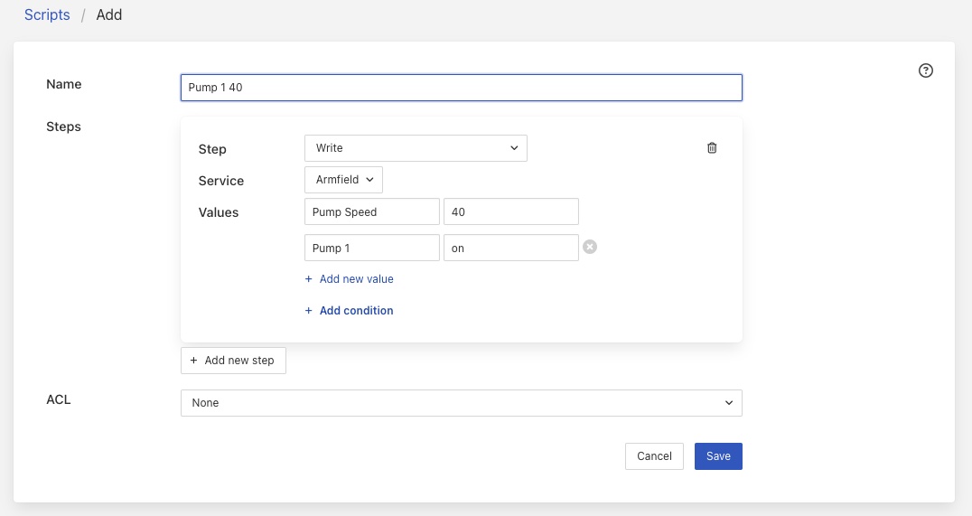
Of course, rather than the defined value of 40 for the pump speed it would usually be a derived or passed in argument to the script.
To stop pump 1 you merely do a write of the single “Pump 1” set point
Write “Pump 2” value “off”
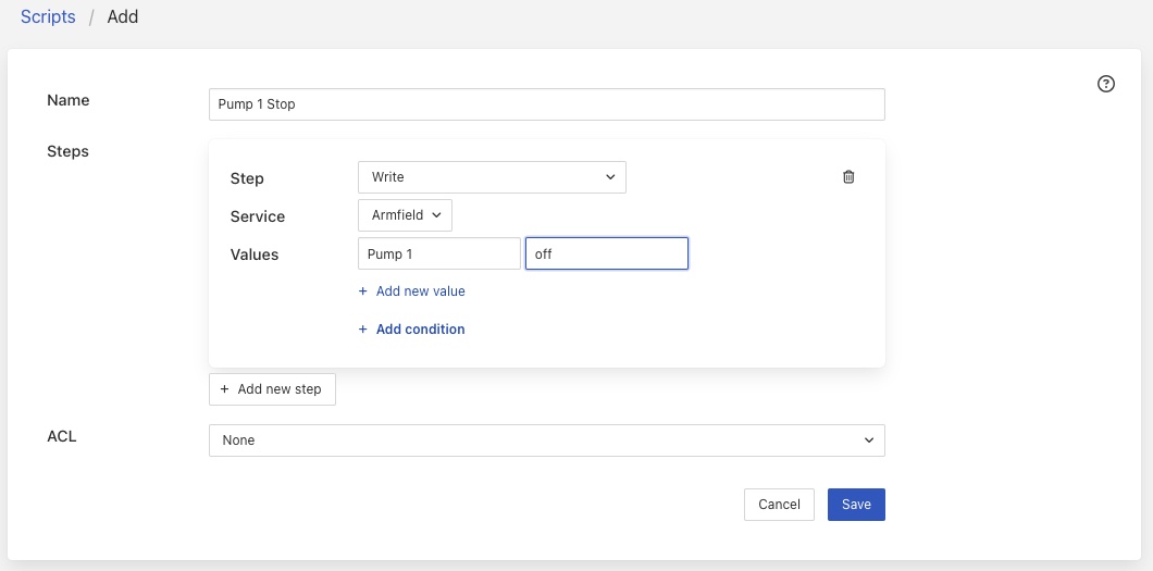
Pump 2 does not require a speed to be set and is merely turn on and off by sending a single write to Pump 2 with the value on or off.
The plugin automatically tracks the state of the bits within a channel and will only change the bit that is set in a control operation. E.g. if a write to set bit 2 of channel 0 is called then the subsequent write of the 8 bits of channel 0 will ensure that the other 7 bits are not modified.
The state of the digital outputs is preserved between invocations of the plugins and hence the preservation of the output status is maintained across restarts of the plugin or FogLAMP.
The plugin automatically takes care of the watchdog functionality and will toggle the watchdog bit whilst the service is running. As soon as the service is stopped or FogLAMP is shutdown the watchdog will stop and the pumps will be turned off.