Data Translation DT9837 Series

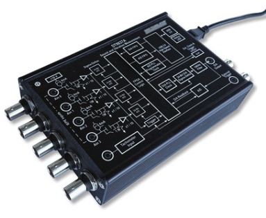
The foglamp-south-dt9837 plugin is a south plugin that is designed to gather data from a Data Translation DT9873 Series DAQ.
To create a south service with the DT9837
Click on South in the left hand menu bar
Select dt9837 from the plugin list
Name your service and click Next
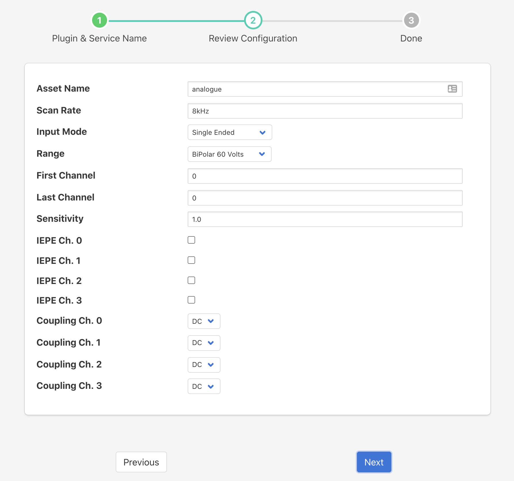
Configure the plugin
Asset Name: The name of the asset that will be created with the values read from the DT9837
Scan Rate: The rate at which each channel is read. This may be expressed as a numeric value, in which case it is the number of samples per second, or it may be expressed in KHz or MHz.
Input Mode: Defines how the input is treated, it may be either a differential pair or a single ended value with a reference ground.
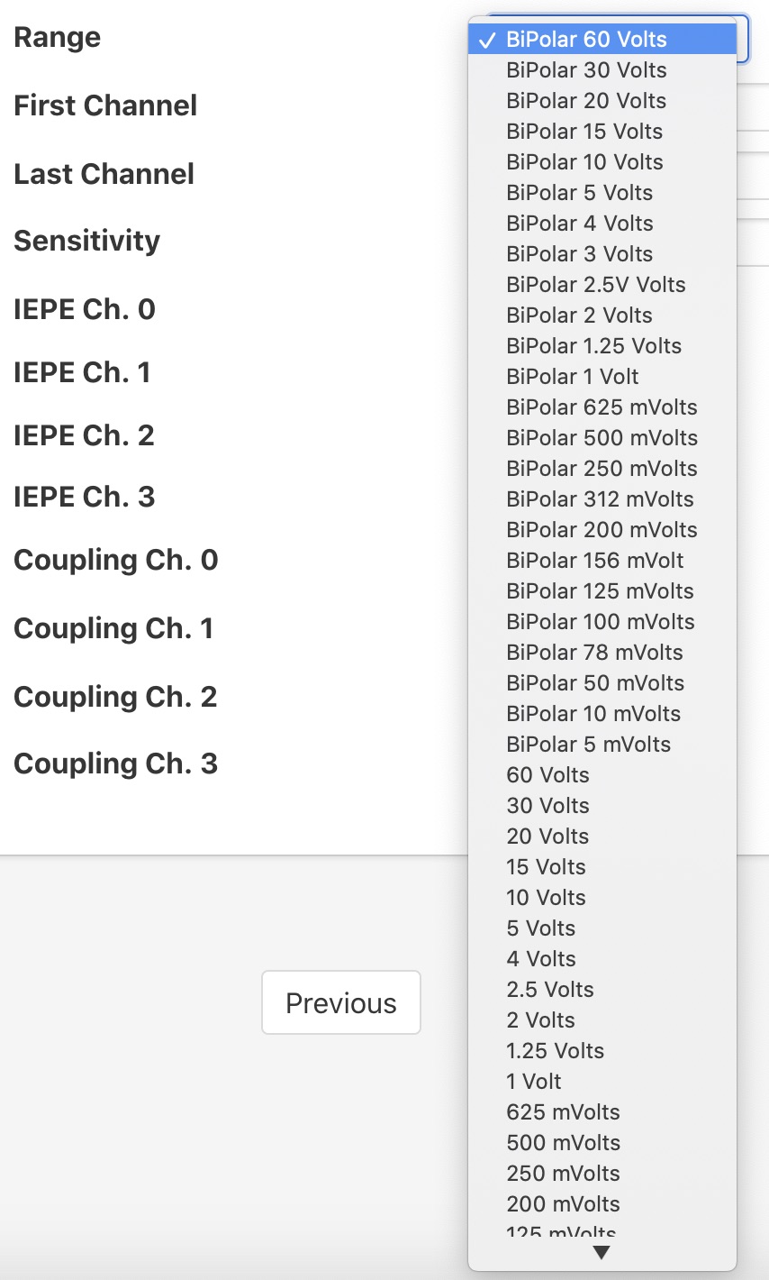
Range: This defines the voltage range for all channels. It may be defined as a bipolar value, in which case it is expected the signal can swing between + and - the specified voltage. A uni-polar value, in which case the voltage swing is between ground and the specified voltage. Or it is a 0 to 20mA current loop.
First Channel: The DT9837 can scan a number of channel in a single operation, these must however be adjunct channels. This option sets the lowest numbered channel to be scanned.
Last Channel: The DT9837 can scan a number of channel in a single operation, these must however be adjunct channels. This option sets the highest numbered channel to be scanned.
Sensitivity: This sets the sensor sensitivity for IEPE sensors attached to any of the channels.
IEPE Ch. 0: Specifies that a IEPE compatible sensor is attached to channel 0.
IEPE Ch. 1: Specifies that a IEPE compatible sensor is attached to channel 1.
IEPE Ch. 2: Specifies that a IEPE compatible sensor is attached to channel 2.
IEPE Ch. 3: Specifies that a IEPE compatible sensor is attached to channel 3.
Coupling Ch. 0: Specifies the input coupling to use for channel 0. This setting has no effect if the channel has been setup for IEPE as IEPE always uses AC coupling.
Coupling Ch. 1: Specifies the input coupling to use for channel 1. This setting has no effect if the channel has been setup for IEPE as IEPE always uses AC coupling.
Coupling Ch. 2: Specifies the input coupling to use for channel 2. This setting has no effect if the channel has been setup for IEPE as IEPE always uses AC coupling.
Coupling Ch. 3: Specifies the input coupling to use for channel 3. This setting has no effect if the channel has been setup for IEPE as IEPE always uses AC coupling.
Click on Next
Enable your service and click on Done


