FogLAMP Control Features
FogLAMP supports facilities that allows control of devices via the south service and plugins. This control in known as set point control as it is not intended for real time critical control of devices but rather to modify the behavior of a device based on one of many different information flows. The latency involved in these control operations is highly dependent on the control path itself and also the scheduling limitations of the underlying operating system. Hence the caveat that the control functions are not real time or guaranteed to be actioned within a specified time window.
Control Functions
The are two type of control function supported
Modify the value in a device via the south service and plugin.
Request the device to perform an action.
Set Point
Setting the value within the device is known as a set point action in FogLAMP. This can be as simple as setting a speed variable within a controller for a fan or it may be more complete. Typically a south plugin would provide a set of values that can be manipulated, giving each a symbolic name that would be available for a set point command. The exact nature of these is defined by the south plugin.
Operation
Operations, as the name implies provides a means for the south service to request a device to perform an operation, such as reset or re-calibrate. The names of these operations and any arguments that can be given are defined within the south plugin and are specific to that south plugin.
Control Paths
Set point control may be invoked via a number of paths with FogLAMP
As the result of a notification within FogLAMP itself.
As a result of a request via the FogLAMP public REST API.
As a result of a control message flowing from a north side system into a north plugin and being routed onward to the south service.
Currently only the notification method is fully implemented within FogLAMP.
The use of a notification in the FogLAMP instance itself provides the fastest response for an edge notification. All the processing for this is done on the edge by FogLAMP itself.
Edge Based Control
Edge based control is the name we use for a class of control applications that take place solely within the FogLAMP instance at the edge. The data that is required for the control decision to be made is gathered in the FogLAMP instance, the logic to trigger the control action runs in the FogLAMP instance and the control action is taken within the FogLAMP instance. Typically this will involve one or more south plugins to gather the data required to make the control decision, possibly some filters to process that data, the notification engine to make the decision and one or more south services to deliver the control messages.
As an example of how edge based control might work lets consider the following case.
We have a machine tool that is being monitored by FogLAMP using the OPC/UA south plugin to read data from the machine tools controlling PLC. As part of that data we receive an asset which contains the temperature of the motor which is running the tool. We can assume this asset is called MotorTemperature and it contains a single data point called temperature.
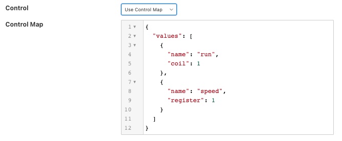
We also have a fan unit that is able to cool that motor which is controlled via a Modbus interface. The modbus contains one a coil that toggles the fan on and off and a register that controls the speed of the fan. We configure the foglamp-south-modbus as a service called MotorFan with a control map that will map the coil and register to a pair of set points.
{
    "values" : [
                   {
                       "name" : "run",
                       "coil" : 1
                   },
                   {
                       "name"     : "speed",
                       "register" : 1
                   }
               ]
}
|
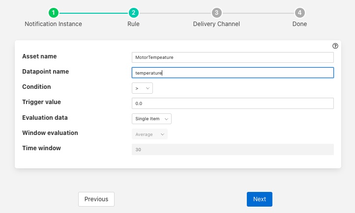
If the measured temperature of the motor going above 35 degrees centigrade we want to turn the fan on at 1200 RPM. We create a new notification to do this. The notification uses the threshold rule and triggers if the asset MotorTemperature, data point temperature is greater than 35.
|
We select the setpoint delivery plugin from the list and configure it.
In Service we set the name of the service we are going to use to control the fan, in this case MotorFan
In Trigger Value we set the control message we are going to send to the service. This will turn the fan on and set the speed to 1200RPM
In Cleared Value we set the control message we are going to send to turn off the fan when the value falls below 35 degrees.
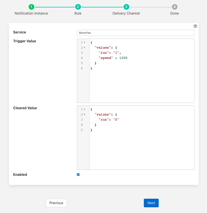
The plugin is enabled and we go on to set the notification type to toggled, since we want to turn off the fan if the motor cools down, and set a retrigger time to prevent the fan switching on and off too quickly. The notification type and the retrigger time are important parameters for tuning the behavior of the control system and are discussed in more detail below.
If we required the fan to speed up at a higher temperature then this could be achieved with a second notification. In this case it would have a higher threshold value and would set the speed to a higher value in the trigger condition and set it back to 1200 in the cleared condition. Since the notification type is toggled the notification service will ensure that these are called in the correct order.
Data Substitution
There is another option that can be considered in our example above that would allow the fan speed to be dependent on the temperature, the use of data substitution in the setpoint notification delivery.
Data substitution allows the values of a data point in the asset that caused the notification rule to trigger to be substituted into the values passed in the set point operation. The data that is available in the substitution is the same data that is given to the notification rule that caused the alert to be triggered. This may be a single asset with all of its data points for simple rules or may be multiple assets for more complex rules. If the notification rule is given averaged data then it is these averages that will be available rather than the individual values.
Parameters are substituted using a simple macro mechanism, the name of an asset and data point with in the asset is inserted into the value surrounded by the $ character. For example to substitute the value of the temperature data point of the MotorTemperature asset into the speed set point parameter we would define the following in the Trigger Value
{
    "values" : {
         "speed"  : "$MotorTemperature.temperature$"
}
Note that we separate the asset name from the data point name using a period character.
This would have the effect of setting the fan speed to the temperature of the motor. Whilst allowing us to vary the speed based on temperature it would probably not be what we want as the fan speed is too low. We need a way to map a temperature to a higher speed.
A simple option is to use the macro mechanism to append a couple of 0s to the temperature, a temperature of 21 degrees would result in a fan speed of 2100 RPM.
{
    "values" : {
         "speed"  : "$MotorTemperature.temperature$00"
}
This works, but is a little primitive and limiting. Another option is to add data to the asset that triggers the notification. In this case we could add an expression filter to create a new data point with a desired fan speed. If we were to add an expression filter and give it the expression desiredSpeed = temperature > 20 ? temperature * 50 + 1200 : 0 then we would create a new data point in the asset called desiredSpeed. The value of desiredSpeed would be 0 if the temperature was 20 degrees or below, however for temperatures above it would be 1200 plus 50 times the temperature.
This new desired speed can then be used to set the temperature in the setpoint notification plugin.
{
    "values" : {
         "speed"  : "$MotorTemperature.desiredSpeed$"
         }
}
The user then has the choice of adding the desired speed item to the data stored in the north, or adding an asset filter in the north to remove this data point form the data that is sent onward to the north.
Tuning edge control systems
The set point control features of FogLAMP are not intended to replace real time control applications such as would be seen in PLCs that are typically implemented in ladder logic, however FogLAMP does allow for high performance control to be implemented within the edge device. The precise latency in control decisions is dependent on a large number of factors and there are various tuning parameters that can be used to reduce the latency in the control path.
In order to understand the latency inherent in the control path we should first start my examining that path to discover where latency can occur. To do this will will choose a simple case of a single south plugin that is gathering data required by a control decision within FogLAMP. The control decision will be taken in a notification rule and delivered via the foglamp-notify-setpoint plugin to another south service.
A total of four services within FogLAMP will be involved in the control path
|
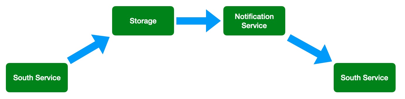
the south service that is gathering the data required for the decision
the storage service that will dispatch the data to the notification service
the notification service that will run the decision rule and trigger the delivery of the control message
the south service that will send the control input to the device that is being controlled
Each of these services can add to that latency in the control path, however the way in which these are configured can significantly reduce that latency.
The south service that is gathering the data will typically being either be polling a device or obtaining data asynchronously from the device. This will be sent to the ingest thread of the south service where it will be buffered before sending the data to the storage service.
The advanced settings for the south service can be used to trigger how often that data is sent to the storage service. Since it is the storage service that is responsible for routing the data onward to the notification service this impacts the latency of the delivery of the control messages.
|
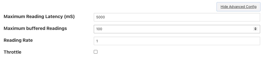
The above shows the default configuration of a south service. In this case data will not be sent to the south service until there are either 100 readings buffered in the south service, or the oldest reading in the south service buffer has been in the buffer for 5000 milliseconds. In this example we are reading 1 new readings every second, therefore will send data to the storage service every 5 seconds, when the oldest reading in the buffer has been there for 5000mS. When it sends data it will send all the data it has buffered, in this case 5 readings as one block. If the oldest reading is the one that triggers the notification we have therefore introduced a 5 second latency into the control path.
The control path latency can be reduced by reducing the Maximum Reading Latency of this south plugin. This will of course put greater load on the system as a whole and should be done with caution as it increases the message traffic between the south service and the storage service.
The storage service has little impact on the latency, it is designed such that it will forward data it receives for buffering to the notification service in parallel to buffering it. The storage service will only forward data the notification service has subscribed to receive and will forward that data in the blocks it arrives at the storage service in. If a block of 5 readings arrives at the the storage service then all 5 will be sent to the notification service as a single block.
The next service in the edge control path is the notification service, this is perhaps the most complex step in the journey. The behavior of the notification service is very dependent upon how each individual notification instance has been configured, factors that are important are the notification type, the retrigger interval and the evaluation data options.
The notification type is used to determine when notifications are delivered to the delivery channel, in the case of edge control this might be the setpoint plugin or the operation plugin. FogLAMP implements three options for the notification type
One shot: A one shot notification is sent once when the notification triggers but will not be resent again if the notification triggers on successive evaluations. Once the evaluation does not trigger, the notification is cleared and will be sent again the next time the notification rule triggers. One shot notifications may be further tailored with a maximum repeat frequency, e.g. no more than once in any 15 minute period.
Toggle: A toggle notification is sent when the notification rule triggers and will not be resent again until the rule fails to trigger, in exactly the same way as a one shot trigger. However in this case when the notification rule first stops triggering a cleared notification is sent. Again this may be modified by the addition of a maximum repeat frequency.
Retriggered: A retriggered notification will continue to be sent when a notification rule triggers. The rate at which the notification is sent can be controlled by a maximum repeat frequency, e.g. send a notification every 5 minutes until the condition fails to trigger.
It is very important to choose the right type of notification in order to ensure the data delivered in your set point control path is what you require. The other factor that comes into play is the Retrigger Time, this defines a dead period during which notifications will not be sent regardless of the notification type.
Setting a retrigger time that is too high will mean that data that you expect to be sent will not be sent. For example if you a new value you wish to be updated once every 5 seconds then you should use a retrigger type notification and set the retrigger time to less than 5 seconds.
It is very important to understand however that the retrigger time defines when notifications can be delivered, it does not related to the interval between readings. As an example, assume we have a retrigger time of 1 second and a reading that arrives every 2 seconds that causes a notification to be sent.
If the south service is left with the default buffering configuration it will send the readings in a block to the storage service every 5 seconds, each block containing 2 readings.
These are sent to the notification service in a single block of two readings.
The notification will evaluate the rule against the first reading in the block.
If the rule triggers the notification service will send the notification via the set point plugin.
The notification service will now evaluate the rule against the second readings.
If the rule triggers the notification service will note that it has been less than 1 second since it sent the last notification and it will not deliver another notification.
Therefore, in this case you appear to see only half of the data points you expect being delivered to you set point notification. In order to rectify this you must alter the tuning parameters of the south service to send data more frequently to the storage service.
The final hop in the edge control path is the call from the notification service to the south service and the delivery via the plugin in the south service. This is done using the south service interface and is run on a separate thread in the south service. The result would normally be expected to be very low latency, however it should be noted that plugins commonly protect against simultaneous ingress and egress, therefore if the south service being used to deliver the data to the end device is also reading data from that device, there may be a requirement for the current read to complete before the write operation an commence.
To illustrate how the buffering in the south service might impact the data sent to the set point control service we will use a simple example of sine wave data being created by a south plugin and have every reading sent to a modbus device and then read back from the modbus device. The input data as read at the south service gathering the data is a smooth sine wave,
|
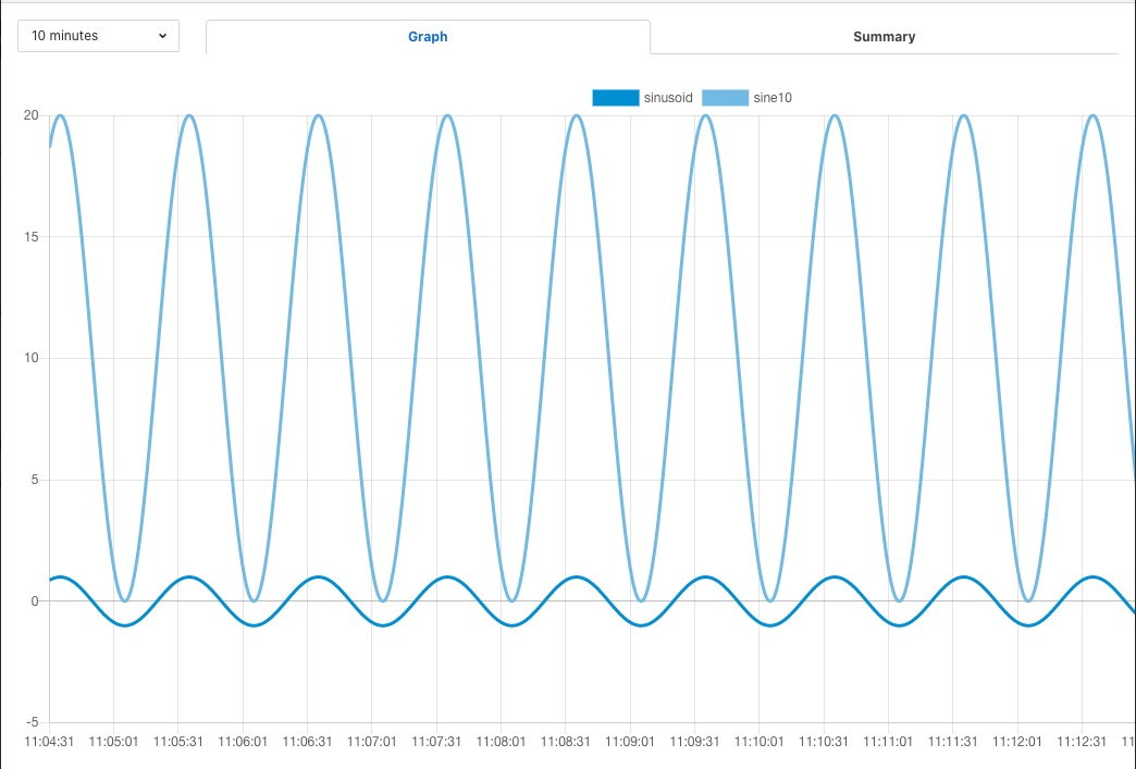
The data observed that is written to the modbus device is not however a clean sine wave as readings have been missed due to the retrigger time eliminating data that arrived in the same buffer.
|
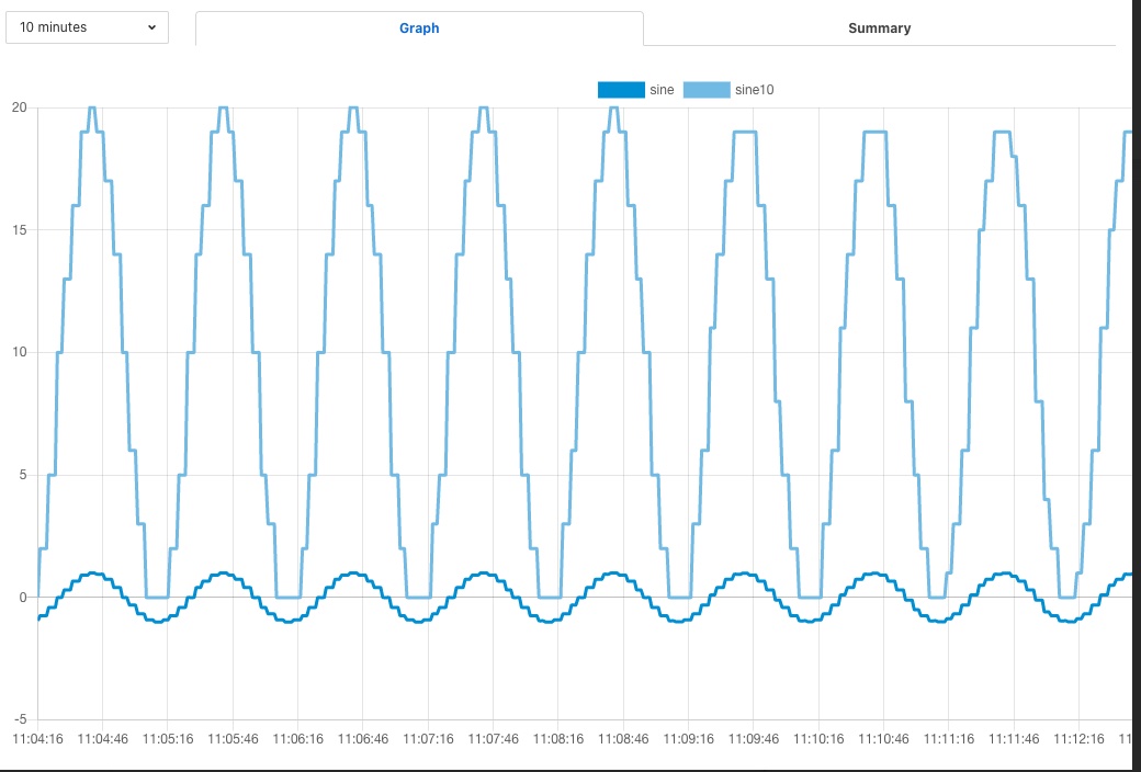
Some jitter caused by occasional differences in the readings that arrive in a single block can be seen in the data as well.
Changing the buffering on the south service to only buffer a single reading results in a much smooth sine wave as can be seen below as the data is seen to transition from one buffering policy to the next.
|
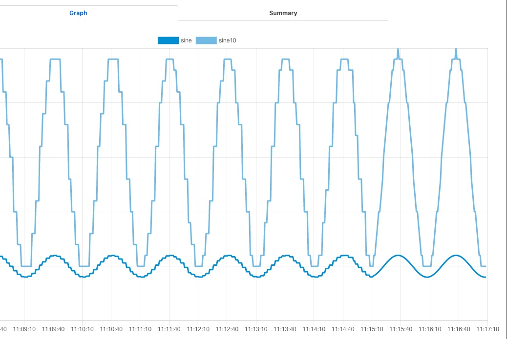
At the left end of the graph the south service is buffering 5 readings before sending data onward, on the right end it is only buffering one reading.
End to End Control
The end to end control path in FogLAMP is a path that allows control messages to enter the FogLAMP system from the north and flow through to the south. Both the north and south plugins involved in the path must support control operations, a dedicated service, the control dispatcher, is used to route the control messages from the source of the control input, the north service to the objects of the control operations, via the south service and plugins. Multiple south services may receive control inputs as a result of a single north control input.
|
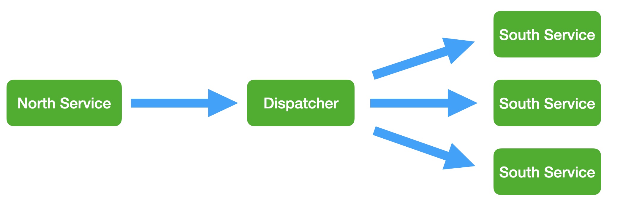
It is the job of the north plugin to define how the control input is received, as this is specific to the protocol of device to the north of FogLAMP. The plugin then takes this input and maps it to a control message that can be routed by the dispatcher. The way this mappings is defined is specific to each of the north plugins that provide control input.
The control messages that the dispatcher is able to route are defined by the following set
Write one or more values to a specified south service
Write one or more values to the south service that ingests a specified asset
Write one or more values to all south services supporting control
Run an automation script within the dispatcher service
Execution an operation on a specified south service
Execute an operation on the south service that ingests a specified asset
Execute an operation on all the south services that support control
A example of how a north plugin might define this mapping is shown below
|
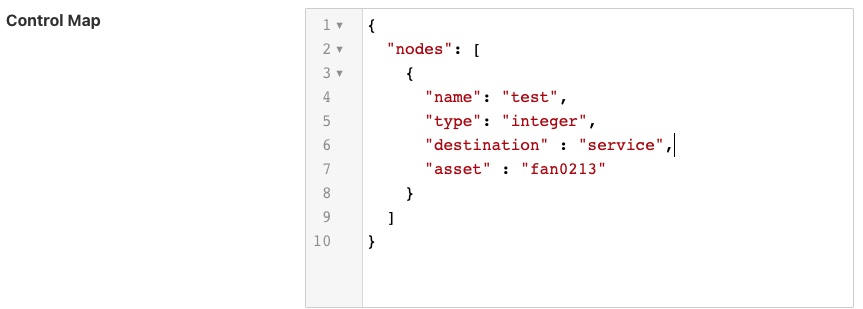
In this case we have an OPCUA north plugin that offers a writable node called test, we have defined this as accepting integer values and also set a destination of service and a name of fan0213. When the OPCUA node test is written the plugin will send a control message to the dispatcher to ask it to perform a write operation on the named service.
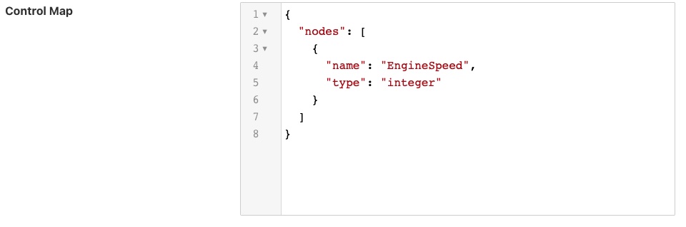
Alternately the dispatcher can send the request based on the assets that the south service is ingesting. In the following example, again taken from the OPCUA north plugin, we send a value of EngineSpeed which is an integer within the OPCUA server that FogLAMP presents to the service that is ingesting the asset pump0014.
|
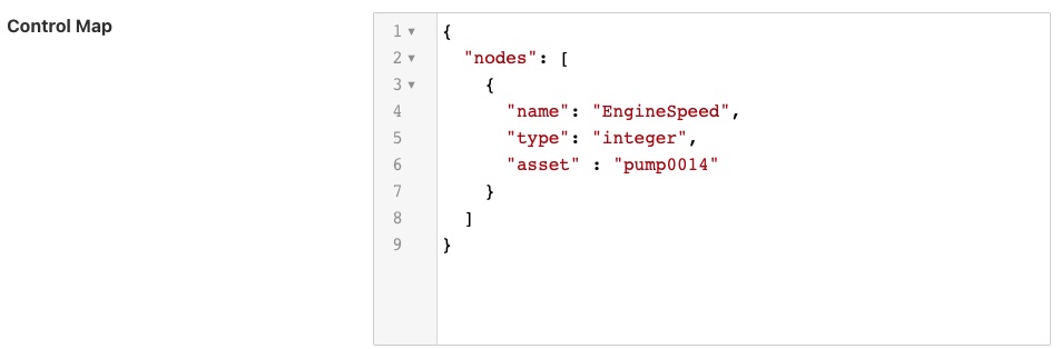
If browsing the OPCUA server which FogLAMP is offering via the north service you will see a node with the browse name EngineSpeed which when written will cause the north plugin to send a message to the dispatcher service and ultimately cause the south service ingesting pump0014 to have that value written to it;s EngineSpeed item. That south service need not be an OPCUA service, it could be any south service that supports control.
|
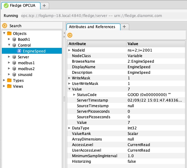
It is also possible to get the dispatcher to send the control request to all services that support control. In the case of the OPCUA north plugin this is specified by omitting the other types of destination.
|
All south services that support control will be sent the request, these may be of many different types and are free to ignore the request if it can not be mapped locally to a resource to update. The semantics of how the request is treated is determined by the south plugin, each plugin receiving the request may take different actions.
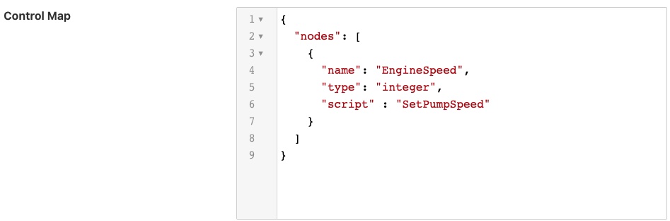
The dispatcher can also be instructed to run a local automation script, these are discussed in more detail below, when a write occurs on the OPCUA node via this north plugin. In this case the control map is passed a script key and name to execute. The script will receive the value EngineSpeed as a parameter of the script.
|
Note, this is an example and does not mean that all or any plugins will use the exact syntax for mapping described above, the documentation for your particular plugin should be consulted to confirm the mapping implemented by the plugin.
Control Dispatcher Service
The control dispatcher service is a service responsible for receiving control messages from other components of the FogLAMP system and taking the necessary actions against the south services in order to achieve the request result. This may be as simple as forwarding the write or operation request to one to more south services or it may require the execution of an automation script by the dispatcher service.
Forwarding Requests
The service dispatcher supports three forwarding regimes which may be used to either forward write requests or operation requests, these are;
Forward to a single service using the name of the service. The caller of the dispatcher must provide the name of the service to which the request will be sent.
Forward to a single service that is responsible for ingesting a named asset into the FogLAMP system. The caller of the dispatcher must provide the name of an asset, the service dispatcher will then look this asset up in the asset tracker database to determine which service ingested the named asset. The request will then be forwarded to that service.
Forward the request to all south services that are currently running and that support control operations. Note that if a service is not running then the request will not be buffered for later sending.
Automation Scripts
The control dispatcher service supports a limited scripting designed to allow users to easily create sequences of operations that can be executed in response to a single control write operation. Scripts are created within FogLAMP and named externally to any control operations and may be executed by more than one control input. These scripts consist of a linear set of steps, each of which results in one of a number of actions, the actions supported are
Perform a write request. A new write operation is defined in the step and it may take the form of any of the three styles of forwarding supported by the dispatcher; write to a named service, write to as service providing an asset or write to all south services.
Perform an operation request on one or all south services. As with the write request above the three forwards of defining the target south service are defined.
Delay the execution of a script. Add a delay between execution of the script steps.
Update the FogLAMP configuration. Change the value of a configuration item within the system.
Execute another script. A mechanism for calling another named script, the named script is executed and then the calling script will continue.
The same data substitution rules described above can also be used within the steps of an automation script. This allows data that is sent to the write or operation request in the dispatcher to be substituted in the steps themselves, for example a request to run a script with the values param1 set to value1 and param2 set to value2 would result in a step that wrote the value $param1$ to a south service actually writing the value value1, i..e the value of param1.
Each step may also have associated with it a condition, if specified that condition must evaluate to true for the step to be executed. If it evaluates to false then the step is not executed and execution moves to the next step in the script.
Graphical Interface
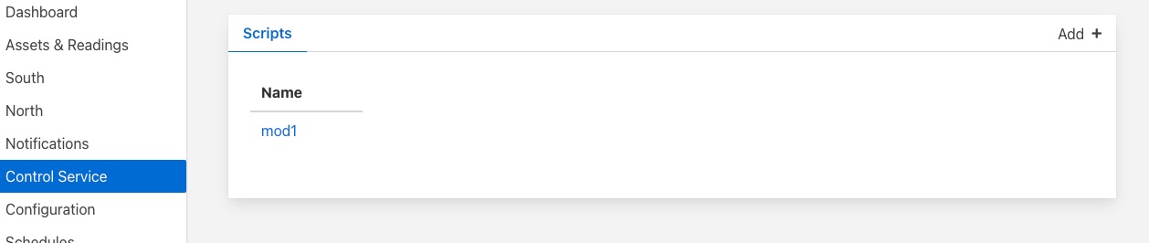
The automation scripts are available via the Control Service menu item in the left hand menu panel. Selecting this will give you access to the user interface associated with the control functions of FogLAMP. Click on the Scripts tab to select the scripts, this will display a list of scripts currently defined within the system and also show an add button icon the top right corner.
|
Viewing & Editing Existing Scripts
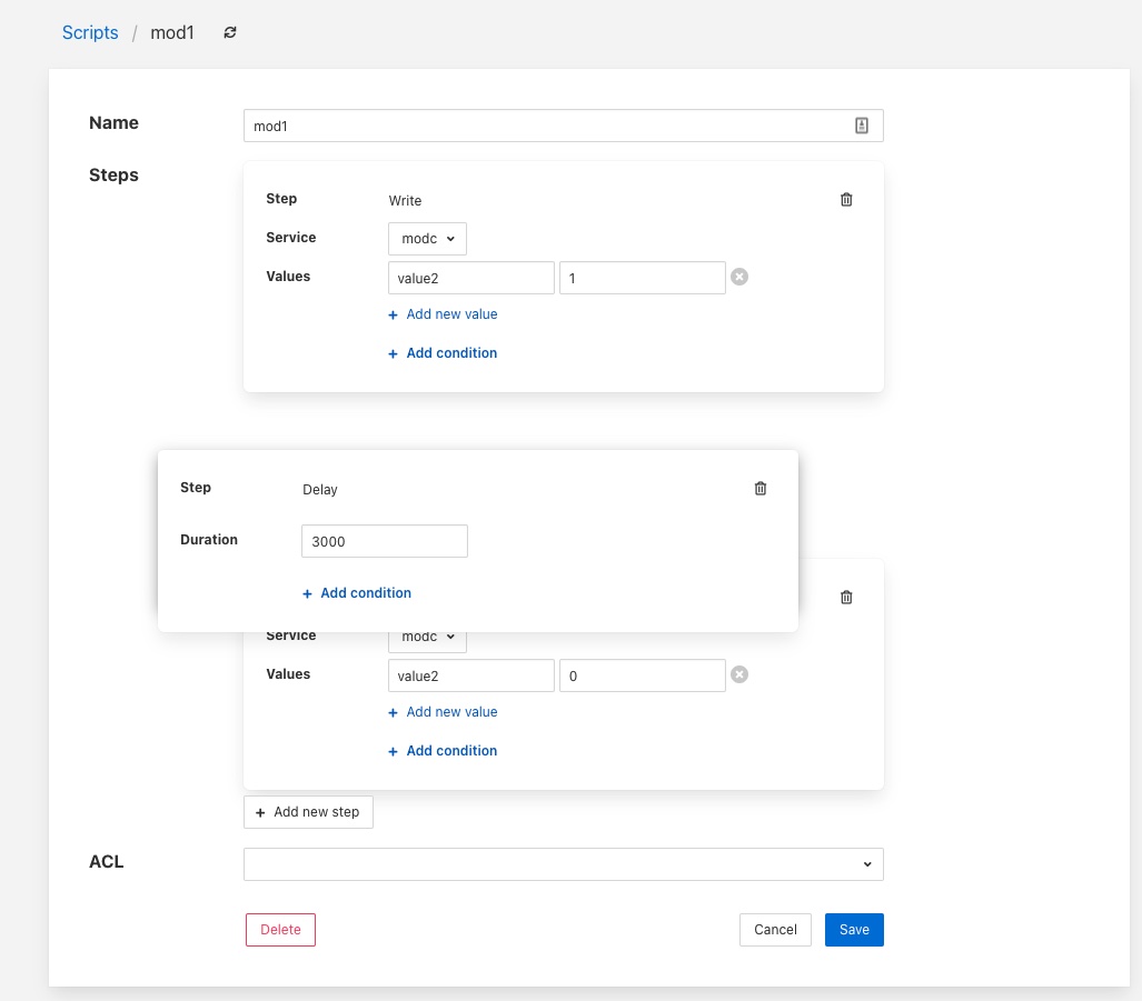
Simply click on the name of a script to view the script
|
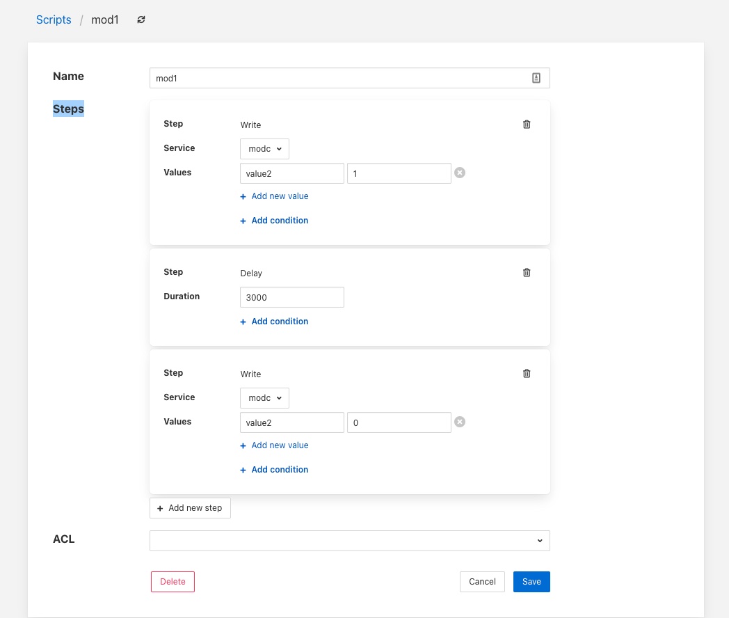
The steps within the script are each displayed within a panel for that step. The user is then able to edit the script provided they have permission on the script.
There are then a number of options that allow you to modify the script, note however it is not possible to change the type of a step in the script. The user must add a new step and remove the old step they wish to replace.
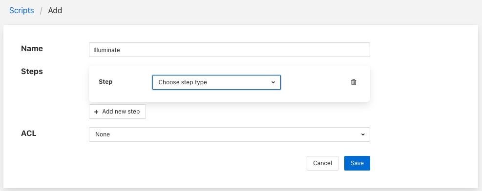
To add a new step to a script click on the Add new step button
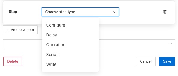
The new step be created in a new panel and will prompt for the user to select the step type
The next step in to process will depend on the type of automation step chosen.
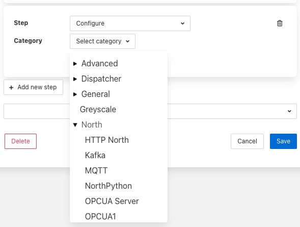
A Configure step will request the configuration category to update to be chosen. This is displayed in a drop down menu.
The configuration categories are shown as a tree structure, allowing the user to navigate to the configuration category they wish to change.
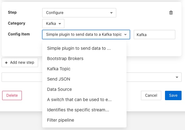
Once chosen the user is presented with the items in that configuration category from which to choose.
Selecting an item will give you a text box with the current value of that item. Simply type the new value that should be assigned to that item when this step of the script runs into that text box.
A Delay step will request the duration of the delay. The Duration is merely typed into the text box and is expressed in milliseconds.
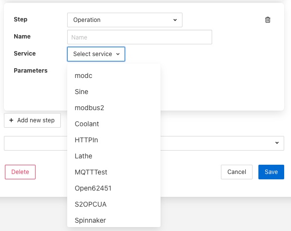
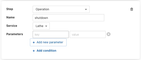
An Operation step will request you to enter the name of the operation to perform and then select the service to which the operation request should be sent
Operations can be passed zero or more parameters, to add parameters to an operation click on the Add parameter option. A pair of text boxes will appear allowing you to enter the key and value for the parameter.
To add another parameter simply press the Add parameter option again.
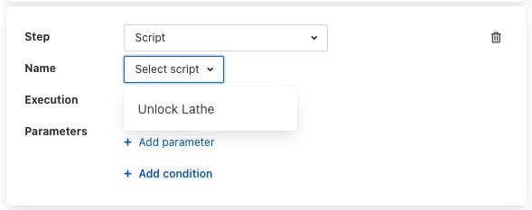
A Script step will request you to choose the name of the script to run from a list of all the currently defined scripts.
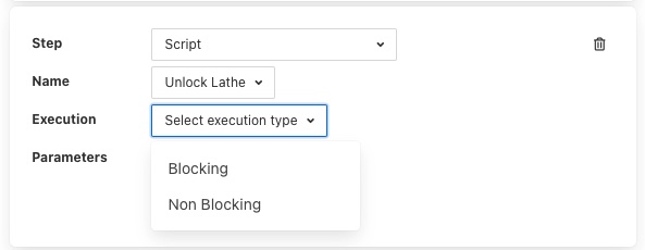
Note that the script that you are currently editing is not included in this list of scripts. You can then choose if you want the execution of this script to block the execution of the current script or to run in parallel with the execution of the current script.
Scripts may also have parameters added by choosing the Add parameter option.
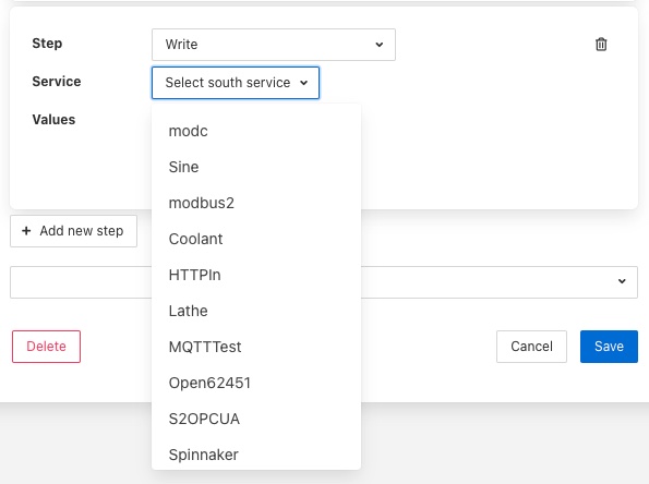
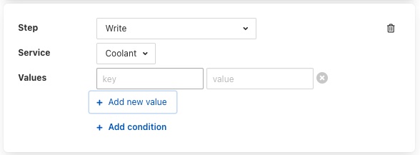
A Write step will request you to choose the service to which you wish to send the write request. The list of available services is given in a drop down selection.
Values are added to the write request by clicking on the Add new value option. This will present a pair of text boxes in which the key and value of the write request value can be typed.
Multiple values can be sent in a single write request, to add another value simply click on the Add new value option again.
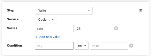
Any step type may have a condition added to it. If a step has a condition associated with it, then that condition must evaluate to true if the step is to be run executed. If it does not evaluate to true the step is skipped and the next step is executed. To add a condition to a step click on the Add condition option within the step’s panel.
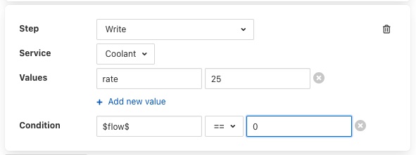
A key and a value text box appears, type the key to test, this is usually a script parameter and the value to test. Script parameters are referenced using the $ character to enclose the name of the script parameter.
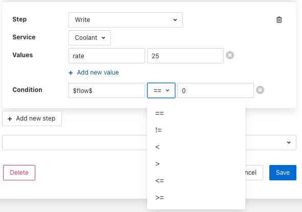
A selection list is provided that allows the test that you wish to perform to be chosen.
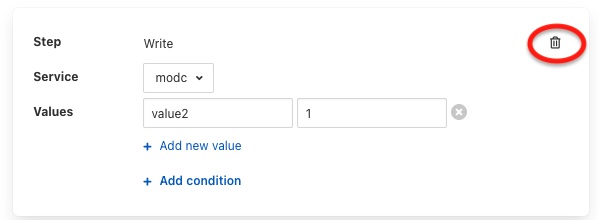
To remove a step from a script click on the bin icon on the right of the step panel
To reorder the steps in a script it is a simple case of clicking on one of the panels that contains a step and dragging and dropping the step into the new position within the script in which it should run.
A script may have an access control list associated to it. This controls how a script can be access, it allows the script to limit access to certain services, notifications or APIs. The creation of ACLs is covered elsewhere, to associate an ACL to a script simply select the name of the ACL from the ACL drop down at foot of the screen. If not ACL is assigned access to the script will not be limited.
Adding a Script
The process for adding new scripts is similar to editing an existing script.
To add a new script click on the Add option in the top right corner.
Enter a name for the script in the text box that appears
Now start to add the steps to you script in the same way as above when editing an existing script.
Once you have added all your steps you may also add optional access control list
Finally click on Save to save your script
Step Conditions
The conditions that can be applied to a step allow for the checking of the values in the original request sent to the dispatcher. For example attaching a condition of the form
speed != 0
to a step, would result in the step being executed if the value in the parameter called speed that was in the original request to the dispatcher, had a value other than 0.
Conditions may be defined using the equals and not equals operators or for numeric values also greater than and less than.
Access Control Lists
Control features within FogLAMP have the ability to add access control to every stage of the control process. Access control lists are used to limit which services have access to specific south services or scripts within the FogLAMP system.
Graphical Interface
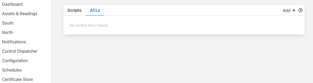
A graphical interfaces is available to allow the creation and management of the access control lists used within the FogLAMP system. This is available within the Control Dispatcher menu item of the FogLAMP graphical interface.
|
Adding An ACL
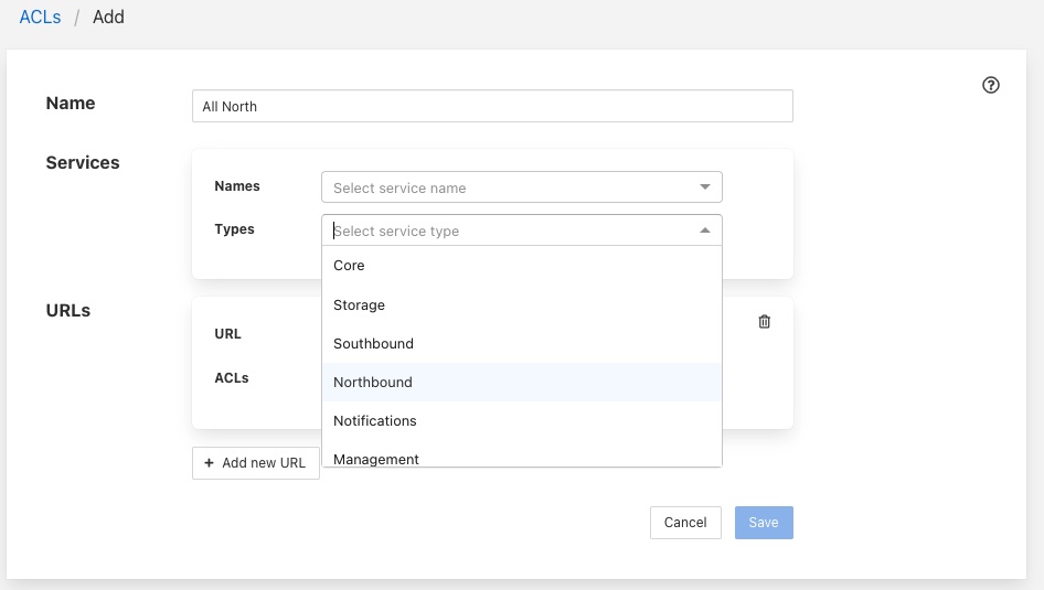
Click on the Add button in the top right corner of the ACL screen, the following screen will then be displayed.
|
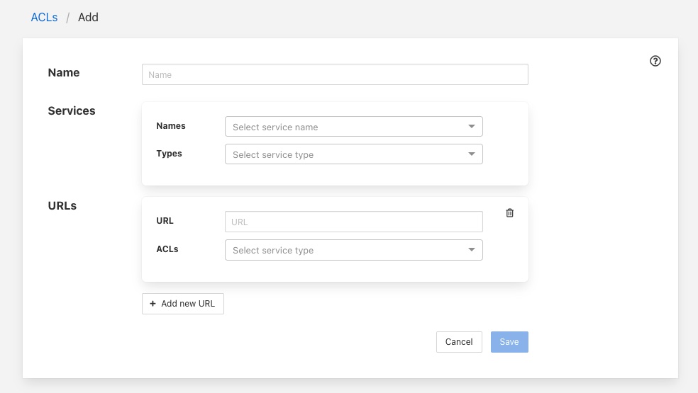
You can enter a name for your access control list in the Name item on the screen. You should give each of your ACLs a unique name, this may be anything you like, but should ideally be descriptive or memorable as this is the name you will use when associating the ACL with services and scripts.
The Services section is use to define a set of services that this ACL is allowing access for. You may select services either by name or by service type. Multiple services may be granted access by a single ACL.
|
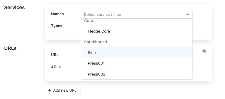
To add a named service to the ACL select the names drop down list and select the service name from those displayed. The display will change to show the service that you added to the ACL.
|
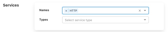
More names may be added to the ACL by selecting the drop down again.
|
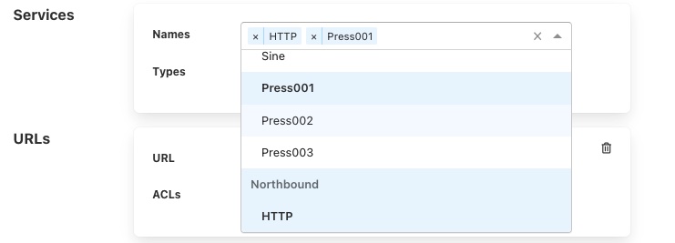
If you wish to remove a named service from the list of services simply click on the small x to the left of the service name you wish to remove.
It is also possible to add a service type to an ACL. In this case all services of this type in the local FogLAMP instance will be given access via this ACL.
|
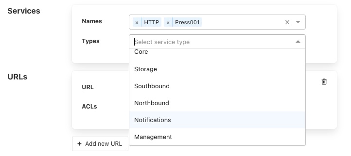
For example to create an ACL that allows all north services to have be granted access you would select Northbound in the Services Types drop down list.
|
The URLs section of the ACL is used to grant access to specific URLs accessing the system.
Note
This is intended to allow control access via the REST API of the FogLAMP instance and is currently not implemented in FogLAMP.
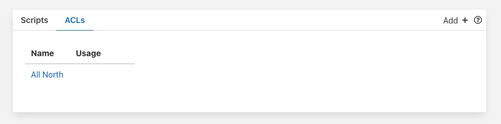
Once you are satisfied with the content of your access control list click on the Save button at the bottom of the page. You will be taken back to a display of the list of ACLs defined in your system.
|
Updating an ACL
In the page that displays the set of ACLs in your system, click on the name of the ACL you wish to update, a page will then be displayed showing the current contents of the ACL.
|
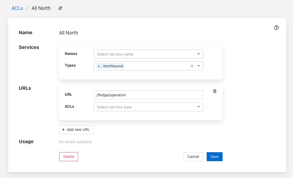
To completely remove the ACL from the system click on the Delete button at the bottom of the page.
You may add and remove service names and types using the same procedure you used when adding the ACL.
Once you are happy with your updated ACL click on the Save button.
Configuration
The control dispatcher service has a small number of configuration items that are available in the Dispatcher configuration category within the general Configuration menu item on the user interface.
Two subcategories exist, Server and Advanced.
Server Configuration
The server section contains a single option which can be used to either turn on or off the forwarding of control messages to the various services within FogLAMP. Clicking this option off will turn off all control message routing within FogLAMP.
Advanced Configuration
|
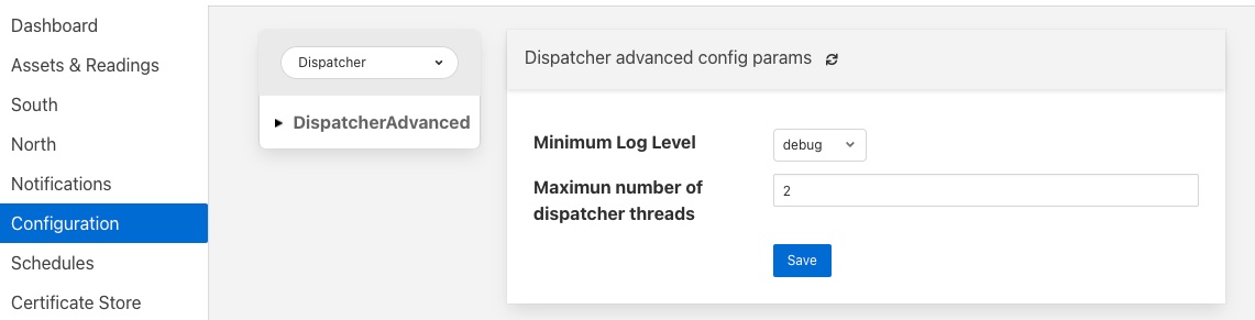
Minimum Log Level: Allows the minimum level at which logs will get written to the system log to be defined.
Maximum number of dispatcher threads: Dispatcher threads are used to execute automation scripts. Each script utilizes a single thread for the duration of the execution of the script. Therefore this setting determines how many scripts can be executed in parallel.