Set Point Control
FogLAMP supports facilities that allows control of devices via the south service and plugins. This control in known as set point control as it is not intended for real time critical control of devices but rather to modify the behavior of a device based on one of many different information flows. The latency involved in these control operations is highly dependent on the control path itself and also the scheduling limitations of the underlying operating system. Hence the caveat that the control functions are not real time or guaranteed to be actioned within a specified time window.
Control Functions
The are two type of control function supported
- Modify the value in a device via the south service and plugin.
- Request the device to perform an action.
Set Point
Setting the value within the device is known as a set point action in FogLAMP. This can be as simple as setting a speed variable within a controller for a fan or it may be more complete. Typically a south plugin would provide a set of values that can be manipulated, giving each a symbolic name that would be available for a set point command. The exact nature of these is defined by the south plugin.
Operation
Operations, as the name implies provides a means for the south service to request a device to perform an operation, such as reset or re-calibrate. The names of these operations and any arguments that can be given are defined within the south plugin and are specific to that south plugin.
Control Paths
Set point control may be invoked via a number of paths with FogLAMP
- As the result of a notification within FogLAMP itself.
- As a result of a request via the FogLAMP public REST API.
- As a result of a control message flowing from a north side system into a north plugin and being routed onward to the south service.
Currently only the notification method is fully implemented within FogLAMP.
The use of a notification in the FogLAMP instance itself provides the fastest response for an edge notification. All the processing for this is done on the edge by FogLAMP itself.
Edge Based Control
Edge based control is the name we use for a class of control applications that take place solely within the FogLAMP instance at the edge. The data that is required for the control decision to be made is gathered in the FogLAMP instance, the logic to trigger the control action runs in the FogLAMP instance and the control action is taken within the FogLAMP instance. Typically this will involve one or more south plugins to gather the data required to make the control decision, possibly some filters to process that data, the notification engine to make the decision and one or more south services to deliver the control messages.
As an example of how edge based control might work lets consider the following case.
We have a machine tool that is being monitored by FogLAMP using the OPC/UA south plugin to read data from the machine tools controlling PLC. As part of that data we receive an asset which contains the temperature of the motor which is running the tool. We can assume this asset is called MotorTemperature and it contains a single data point called temperature.
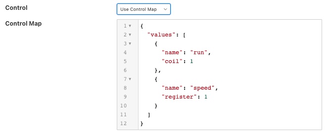
We also have a fan unit that is able to cool that motor which is controlled via a Modbus interface. The modbus contains one a coil that toggles the fan on and off and a register that controls the speed of the fan. We configure the foglamp-south-modbus as a service called MotorFan with a control map that will map the coil and register to a pair of set points.
{
    "values" : [
                   {
                       "name" : "run",
                       "coil" : 1
                   },
                   {
                       "name"     : "speed",
                       "register" : 1
                   }
               ]
}
 |
If the measured temperature of the motor going above 35 degrees centigrade we want to turn the fan on at 1200 RPM. We create a new notification to do this. The notification uses the threshold rule and triggers if the asset MotorTemperature, data point temperature is greater than 35.
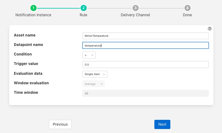 |
We select the setpoint delivery plugin from the list and configure it.
- In Service we set the name of the service we are going to use to control the fan, in this case MotorFan
- In Trigger Value we set the control message we are going to send to the service. This will turn the fan on and set the speed to 1200RPM
- In Cleared Value we set the control message we are going to send to turn off the fan when the value falls below 35 degrees.
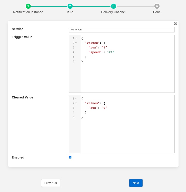
The plugin is enabled and we go on to set the notification type to toggled, since we want to turn off the fan if the motor cools down, and set a retrigger time to prevent the fan switching on and off too quickly. The notification type and the retrigger time are important parameters for tuning the behavior of the control system and are discussed in more detail below.
If we required the fan to speed up at a higher temperature then this could be achieved with a second notification. In this case it would have a higher threshold value and would set the speed to a higher value in the trigger condition and set it back to 1200 in the cleared condition. Since the notification type is toggled the notification service will ensure that these are called in the correct order.
Data Substitution
There is another option that can be considered in our example above that would allow the fan speed to be dependent on the temperature, the use of data substitution in the setpoint notification delivery.
Data substitution allows the values of a data point in the asset that caused the notification rule to trigger to be substituted into the values passed in the set point operation. The data that is available in the substitution is the same data that is given to the notification rule that caused the alert to be triggered. This may be a single asset with all of its data points for simple rules or may be multiple assets for more complex rules. If the notification rule is given averaged data then it is these averages that will be available rather than the individual values.
Parameters are substituted using a simple macro mechanism, the name of an asset and data point with in the asset is inserted into the value surrounded by the $ character. For example to substitute the value of the temperature data point of the MotorTemperature asset into the speed set point parameter we would define the following in the Trigger Value
{
    "values" : {
         "speed"  : "$MotorTemperature.temperature$"
}
Note that we separate the asset name from the data point name using a period character.
This would have the effect of setting the fan speed to the temperature of the motor. Whilst allowing us to vary the speed based on temperature it would probably not be what we want as the fan speed is too low. We need a way to map a temperature to a higher speed.
A simple option is to use the macro mechanism to append a couple of 0s to the temperature, a temperature of 21 degrees would result in a fan speed of 2100 RPM.
{
    "values" : {
         "speed"  : "$MotorTemperature.temperature$00"
}
This works, but is a little primitive and limiting. Another option is to add data to the asset that triggers the notification. In this case we could add an expression filter to create a new data point with a desired fan speed. If we were to add an expression filter and give it the expression desiredSpeed = temperature > 20 ? temperature * 50 + 1200 : 0 then we would create a new data point in the asset called desiredSpeed. The value of desiredSpeed would be 0 if the temperature was 20 degrees or below, however for temperatures above it would be 1200 plus 50 times the temperature.
This new desired speed can then be used to set the temperature in the setpoint notification plugin.
{
    "values" : {
         "speed"  : "$MotorTemperature.desiredSpeed$"
         }
}
The user then has the choice of adding the desired speed item to the data stored in the north, or adding an asset filter in the north to remove this data point form the data that is sent onward to the north.
Tuning edge control systems
The set point control features of FogLAMP are not intended to replace real time control applications such as would be seen in PLCs that are typically implemented in ladder logic, however FogLAMP does allow for high performance control to be implemented within the edge device. The precise latency in control decisions is dependent on a large number of factors and there are various tuning parameters that can be used to reduce the latency in the control path.
In order to understand the latency inherent in the control path we should first start my examining that path to discover where latency can occur. To do this will will choose a simple case of a single south plugin that is gathering data required by a control decision within FogLAMP. The control decision will be taken in a notification rule and delivered via the foglamp-notify-setpoint plugin to another south service.
A total of four services within FogLAMP will be involved in the control path
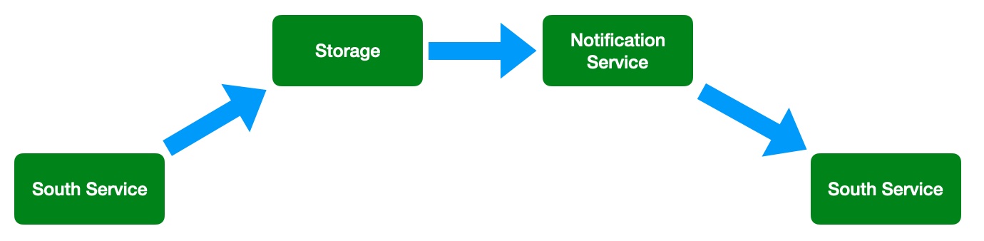 |
- the south service that is gathering the data required for the decision
- the storage service that will dispatch the data to the notification service
- the notification service that will run the decision rule and trigger the delivery of the control message
- the south service that will send the control input to the device that is being controlled
Each of these services can add to that latency in the control path, however the way in which these are configured can significantly reduce that latency.
The south service that is gathering the data will typically being either be polling a device or obtaining data asynchronously from the device. This will be sent to the ingest thread of the south service where it will be buffered before sending the data to the storage service.
The advanced settings for the south service can be used to trigger how often that data is sent to the storage service. Since it is the storage service that is responsible for routing the data onward to the notification service this impacts the latency of the delivery of the control messages.
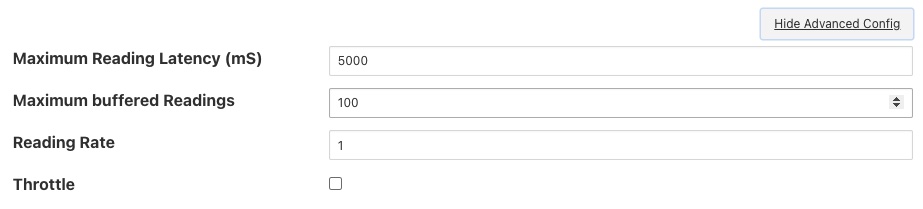 |
The above shows the default configuration of a south service. In this case data will not be sent to the south service until there are either 100 readings buffered in the south service, or the oldest reading in the south service buffer has been in the buffer for 5000 milliseconds. In this example we are reading 1 new readings every second, therefore will send data to the storage service every 5 seconds, when the oldest reading in the buffer has been there for 5000mS. When it sends data it will send all the data it has buffered, in this case 5 readings as one block. If the oldest reading is the one that triggers the notification we have therefore introduced a 5 second latency into the control path.
The control path latency can be reduced by reducing the Maximum Reading Latency of this south plugin. This will of course put greater load on the system as a whole and should be done with caution as it increases the message traffic between the south service and the storage service.
The storage service has little impact on the latency, it is designed such that it will forward data it receives for buffering to the notification service in parallel to buffering it. The storage service will only forward data the notification service has subscribed to receive and will forward that data in the blocks it arrives at the storage service in. If a block of 5 readings arrives at the the storage service then all 5 will be sent to the notification service as a single block.
The next service in the edge control path is the notification service, this is perhaps the most complex step in the journey. The behavior of the notification service is very dependent upon how each individual notification instance has been configured, factors that are important are the notification type, the retrigger interval and the evaluation data options.
The notification type is used to determine when notifications are delivered to the delivery channel, in the case of edge control this might be the setpoint plugin or the operation plugin. FogLAMP implements three options for the notification type
- One shot: A one shot notification is sent once when the notification triggers but will not be resent again if the notification triggers on successive evaluations. Once the evaluation does not trigger, the notification is cleared and will be sent again the next time the notification rule triggers. One shot notifications may be further tailored with a maximum repeat frequency, e.g. no more than once in any 15 minute period.
- Toggle: A toggle notification is sent when the notification rule triggers and will not be resent again until the rule fails to trigger, in exactly the same way as a one shot trigger. However in this case when the notification rule first stops triggering a cleared notification is sent. Again this may be modified by the addition of a maximum repeat frequency.
- Retriggered: A retriggered notification will continue to be sent when a notification rule triggers. The rate at which the notification is sent can be controlled by a maximum repeat frequency, e.g. send a notification every 5 minutes until the condition fails to trigger.
It is very important to choose the right type of notification in order to ensure the data delivered in your set point control path is what you require. The other factor that comes into play is the Retrigger Time, this defines a dead period during which notifications will not be sent regardless of the notification type.
Setting a retrigger time that is too high will mean that data that you expect to be sent will not be sent. For example if you a new value you wish to be updated once every 5 seconds then you should use a retrigger type notification and set the retrigger time to less than 5 seconds.
It is very important to understand however that the retrigger time defines when notifications can be delivered, it does not related to the interval between readings. As an example, assume we have a retrigger time of 1 second and a reading that arrives every 2 seconds that causes a notification to be sent.
- If the south service is left with the default buffering configuration it will send the readings in a block to the storage service every 5 seconds, each block containing 2 readings.
- These are sent to the notification service in a single block of two readings.
- The notification will evaluate the rule against the first reading in the block.
- If the rule triggers the notification service will send the notification via the set point plugin.
- The notification service will now evaluate the rule against the second readings.
- If the rule triggers the notification service will note that it has been less than 1 second since it sent the last notification and it will not deliver another notification.
Therefore, in this case you appear to see only half of the data points you expect being delivered to you set point notification. In order to rectify this you must alter the tuning parameters of the south service to send data more frequently to the storage service.
The final hop in the edge control path is the call from the notification service to the south service and the delivery via the plugin in the south service. This is done using the south service interface and is run on a separate thread in the south service. The result would normally be expected to be very low latency, however it should be noted that plugins commonly protect against simultaneous ingress and egress, therefore if the south service being used to deliver the data to the end device is also reading data from that device, there may be a requirement for the current read to complete before the write operation an commence.
To illustrate how the buffering in the south service might impact the data sent to the set point control service we will use a simple example of sine wave data being created by a south plugin and have every reading sent to a modbus device and then read back from the modbus device. The input data as read at the south service gathering the data is a smooth sine wave,
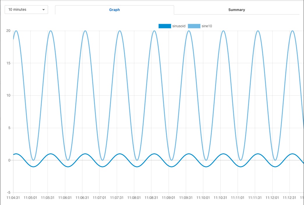 |
The data observed that is written to the modbus device is not however a clean sine wave as readings have been missed due to the retrigger time eliminating data that arrived in the same buffer.
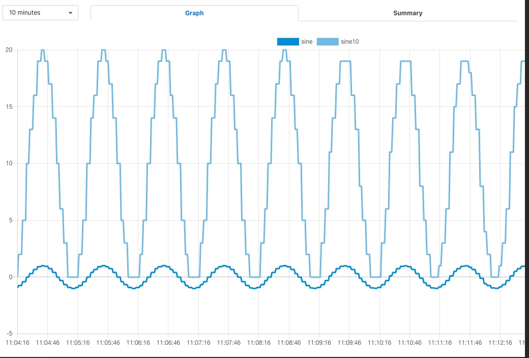 |
Some jitter caused by occasional differences in the readings that arrive in a single block can be seen in the data as well.
Changing the buffering on the south service to only buffer a single reading results in a much smooth sine wave as can be seen below as the data is seen to transition from one buffering policy to the next.
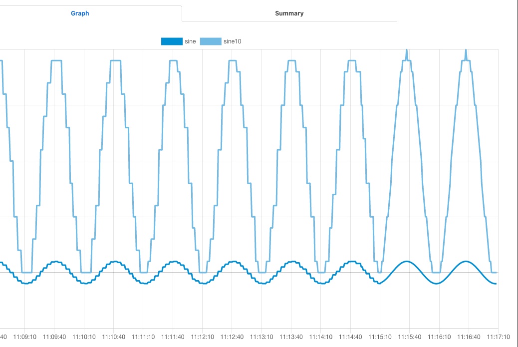 |
At the left end of the graph the south service is buffering 5 readings before sending data onward, on the right end it is only buffering one reading.